Field of Application
- Measurement and characterization of blade vibrations in turbomachinery in operation
- Crack detection
- Mistuning detection
Description
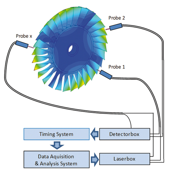
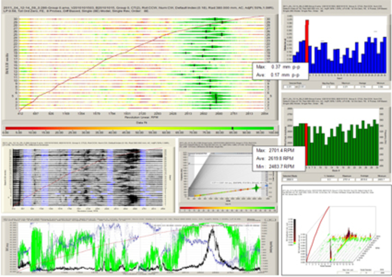
The system present at the TFD is an optical laser measurement method that works according to the light barrier principle. Several sensors mounted around the circumference in the housing emit a laser beam that is reflected by the blade tip as it passes through the blades. This scattered light is directed via fiber optics to a detector. This allows the time of arrival of the blades at the sensor positions to be measured. If blade vibrations occur, the arrival time deviates from the arrival time of the non-vibrating blade due to a leading or lagging of the deflected blade tip, depending on the vibration state. From this time difference, the deflection of the blade can be determined. By using a total of eight probes, up to three simultaneously occurring blade vibrations can be recorded. With the extensive online and offline analysis software, both synchronous (forced response) and non-synchronous vibrations (flutter, stall/surge) can be evaluated in detail. The system is also suitable for the detection of blade cracks (crack detection), as this changes the vibration characteristics of the blade, which in turn can be recorded.
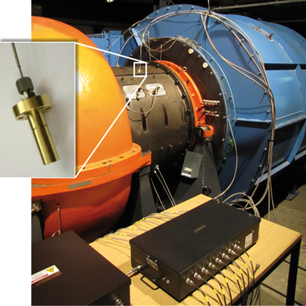
By using high-temperature probes, measurements in the high-temperature range can also be carried out at the institute, e.g. on turbocharger turbines.
Advantages of the Tip Timing System over conventional strain gauge measurements include:
- Non-invasive nature of the system, which avoids any influence on the vibration system from both a mechanical and aerodynamic point of view.
- Acquisition of all blades without great instrumentation effort. This makes the measurement method particularly suitable for mistuning investigations.
- Telemetry is not required as the probes are mounted in the housing.
Our system is a mobile system, which can be used at all test stands of the TFD.
This measurement method can also be found in the literature under the names Non-Intrusive Stress Measurement (NSMS), Arrival Time Analysis (ATA), Blade Tip Timing (BTT) or Non-Contact Blade Vibration Measurement (BSSM).
For further information on the TFD's tip timing system used, please visit the manufacturer's website of Agilis Measurement Systems, Inc.
Measurement Parameter
- Resonance frequency
- Resonance speed
- Amplitude
- Phase
- Engine Order
- Node diameter
- Attenuation
Contact


Aeroacoustics, Aeroelasticity and Wind Energy
30823 Garbsen
Aeroacoustics, Aeroelasticity and Wind Energy


30823 Garbsen


