Field of Application
- Application of inlet guide vanes
- Variation of the volute geometry
- Flexible application of optical measurement techniques (L2F, PIV)
Description
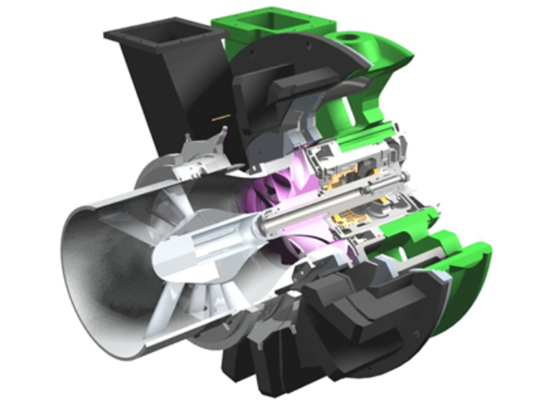
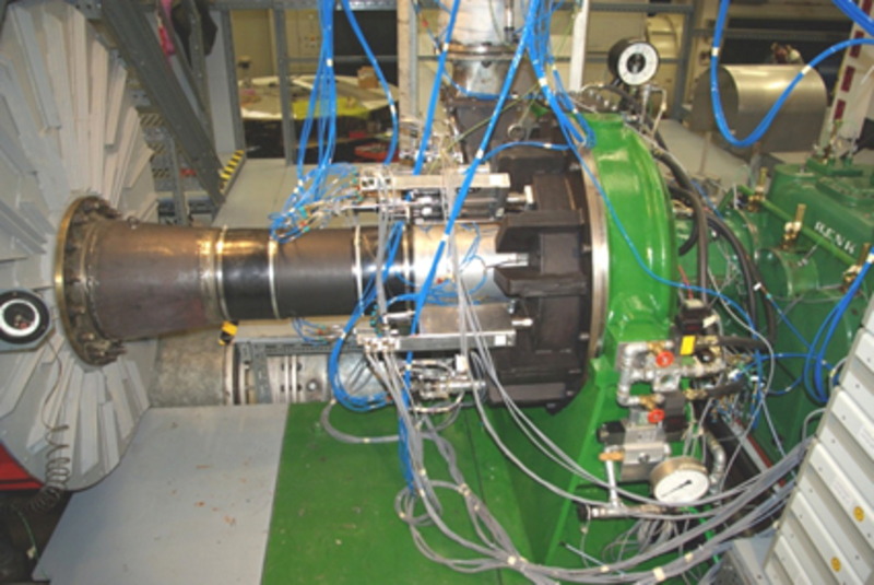
The test rig of the large centrifugal compressor (LCC) has a modular single stage design which allows a wide variety of studies. For example there are different compressor wheels, diffusers, and inlet guide vanes available.
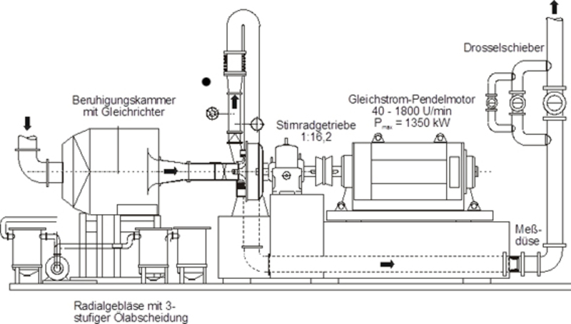
A special feature of the test rig is its closed-loop capability. In closed-loop configuration the air intake can be throttled, reducing the inlet pressure below ambient. This reduces the power needed for a desired pressure ratio.
The test rig can be simply described as follows. Air is sucked in from the ambient atmosphere and runs through a settling chamber with a flow straightener. From the flow straightener the air is directed to the inlet guide vane (IGV) system and in the compressor wheel. In the subsequent diffuser the air is decelerated leading to an increased static pressure. Afterwards the air is collected in a volute and leaves the test rig through a exhaust chimney pipe system. In closed-loop operation mode the pressurized air is cooled in a heat exchanger and reenters the test rig in front of the settling chamber.
Measurement Techniques
- Steady and unsteady pressure measurement techniques
- Temperature measurement techniques (Type K and PT100)
- Torque shaft measurement techniques
- Acceleration sensors for vibration monitoring
- CTA and CCA probes for measuring velocity vectors and flow field turbulence
- PIV – Particle Image Velocimetry
- L2F – Laser 2 Focus
Specifications
| Output power | 1350 kW |
| Rotational speed | 18.000 1/min |
| Mass flow | 9 kg/s |
| Total pressure ratio | 2,4 |
| Max. isentropic efficiency | 85 % |
| Impeller diameter | 400 mm |
| Max. tip speed Mach number | 1,12 |
| Load coefficient | 0.25 - 1,3 |


