Digital Image Correlation (DIC)

Digital Image Correlation (DIC) is a non-invasive, optical measurement technique used to track movements of surface structures over time.

Field of Application

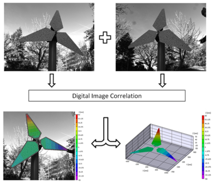
  • Contactless measurement of surface deformations in rotating machinery
  • Measurement of rotor blade deformations on wind turbines in operation
  • Stress analysis and modal analysis on machine components

Description

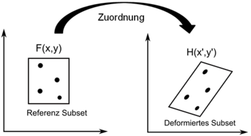
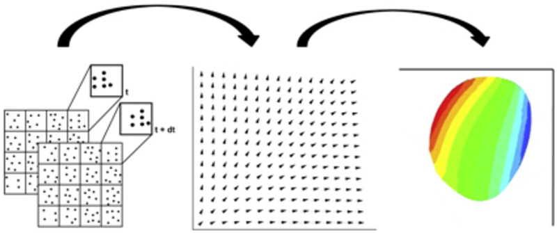
Starting from a reference image, the movement of the surface over time relative to the reference is determined. By isolating or eliminating the rigid body motion, the strain can be calculated and, with the help of material laws, the stress on the component surface. Likewise, large-scale vibration analyses on stationary and rotating components are possible through the use of high-speed cameras.

The basic requirement for the use of Digital Image Correlation is a random, high-contrast, non-reflective surface texture. If the natural texture of the surface does not meet these requirements, artificial textures can be applied. The possibilities range from printed foils, to sprayed-on textures, to surfaces wetted with toner.

To evaluate the measurement images, the random texture of the surface in the reference image is discretized into windows (also called "subsets"). These subsets are then assigned to each image in the measurement series using a correlation method. The result is a vector field that assigns a displacement to each subset relative to the reference. By using subpixel interpolation, movements in the image down to 0.01 pixel can be detected.

The method works both with only one camera in two-dimensional space and in three-dimensional space with at least two cameras. When using a single camera, the camera's line of sight must be perpendicular to the surface being examined and only in-plane motion can be detected. Two cameras, on the other hand, allow tracking of a surface in three-dimensional space. In addition, for two or more cameras, the restriction of the perpendicular viewing direction to the surface does not apply. Even relatively acute viewing angles to the surface can often be realized.

Measurement Parameter

  • Deformation
  • Elongation
  • Stresses
  • Absorption
  • Frequencies (FFT)
Picture - Subset in reference image without deformation (left) and assigned subset in image of measurement series with deformation (right) Picture - Subset in reference image without deformation (left) and assigned subset in image of measurement series with deformation (right) Picture - Subset in reference image without deformation (left) and assigned subset in image of measurement series with deformation (right)
Subset in reference image without deformation (left) and assigned subset in image of measurement series with deformation (right)
Picture - Assignment of subsets between reference and measurement image (left). Vector field shows displacement of all subsets between reference and measurement image (center). Material laws are used to calculate the stress on the surface (right). Picture - Assignment of subsets between reference and measurement image (left). Vector field shows displacement of all subsets between reference and measurement image (center). Material laws are used to calculate the stress on the surface (right). Picture - Assignment of subsets between reference and measurement image (left). Vector field shows displacement of all subsets between reference and measurement image (center). Material laws are used to calculate the stress on the surface (right).
Assignment of subsets between reference and measurement image (left). Vector field shows displacement of all subsets between reference and measurement image (center). Material laws are used to calculate the stress on the surface (right).
Picture - Use of Digital Image Correlation at the test bench for rotor blade deformations Picture - Use of Digital Image Correlation at the test bench for rotor blade deformations Picture - Use of Digital Image Correlation at the test bench for rotor blade deformations
Use of Digital Image Correlation at the test bench for rotor blade deformations

Contact

Jan Gößling, M.Sc.
Research Staff
Address
An der Universität 1
30823 Garbsen
Building
Room
207
Jan Gößling, M.Sc.
Research Staff
Address
An der Universität 1
30823 Garbsen
Building
Room
207