Field of Application
- Research of aerodynamic effects on neighboring zones
- Transition investigation
- Investigation of aeroelastic fundamentals
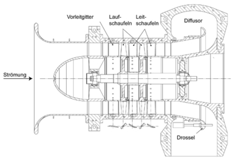
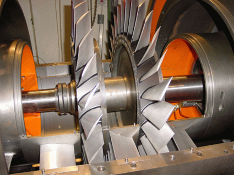
Description
This two-stage compressor operates within a closed-loop circuit. In order to adjust and define the boundary conditions at the compressor inlet, the air temperature can be controlled and set as a constant in the condenser. The stator blades are instrumented with a hot-film array that allows the investigation of transition dependent on the upstream and downstream perturbations induced by the rotor blades. The low ratio of thickness and span of the LSAC allows the research of the fundamentals of aeroelasticity. Piezoelectric actuators are used to excite blade vibrations during the design concept. The rotor blade vibrations can then be measured by means of a strain gauge, and also through the tip-timing system.
Measurement Techniques
- Steady and unsteady measurement techniques.
- Temperature measurement techniques (Type K and PT100).
- Torque shaft measurement techniques.
- Acceleration sensors for vibration monitoring.
- Hot-film array for wall shear stress measurements.
- Radial-periphery pocket with steady and unsteady multi-hole probes behind each stator row.
- Radial pocket with steady and unsteady multi-hole probes behind each rotor row.
- CTA and CCA probes for measuring velocity vectors and flow field turbulence.
- Strain gauge to measure blade vibrations.
- Tip timing for blade vibration measurement.
Specifications
| Output power | 450 kW |
| Rotational speed | 3.000 1/min |
| Mass flow | 16,5 kg/s |
| Total pressure ratio | 1,08 |
| No. Stages | 2 |
| Hub ratio | 0,63 |
| Thickness-span ratio | 0.064 (Hub), 0.043 (Blade tip) |
| Axial velocity in meridian plane | 55,5 m/s |
Contact


Dipl.-Ing. Henning Rätz
Research Staff
Management DEW
Management DEW
Phone
Fax
Email
Address
An der Universität 1
30823 Garbsen
30823 Garbsen
Building
Room
Dipl.-Ing. Henning Rätz
Research Staff
Management DEW
Management DEW

Dr.-Ing. Dajan Mimic
Group Leader
Compressor
Compressor
Phone
Fax
Email
Address
An der Universität 1
30823 Garbsen
30823 Garbsen
Building
Room
Dr.-Ing. Dajan Mimic
Group Leader
Compressor
Compressor


