Field of Application
- Investigation of the inflow parameters on the operating behavior of exhaust diffusers
- Investigation of the influence of the supporting rib on secondary flows in annular diffusers
Description
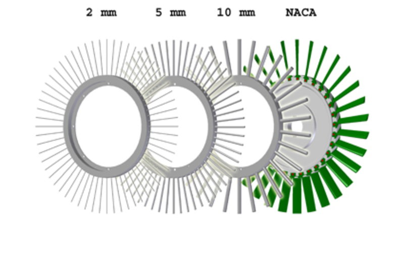
Air from the atmosphere is sucked into the annular diffuser using a continuously adjustable swirl generator and redirected to the axial direction either with or without struts. A rotating spoke is used in the annular diffuser as a wake generator to model the realistic turbulent flow exhausted by a turbine. An additional circumferential flow over the spoke allows the simulation of tip leakage flow. The air flow then passes through a conical diffuser into a chamber containing a honeycomb. The various operating parameters include mass flow rate, rotational speed of the wake generator spoke, inlet swirl, the mass and angular momentum flow rate of the gap flow.
The design procedure of a more efficient exhaust diffuser benefits from intensive experimental investigation. The flow in an exhaust diffuser is typically dominated by unsteady effects in the last stage of the turbine and the supporting rib. This complex flow field is dependent on the turbine operating conditions and must be well understood in order to improve efficiency. Both stationary and unsteady measurement techniques are used to investigate the flow field. Based on the results of the research, the design procedure can be improved.
Measurement Techniques
- Steady and unsteady pressure measurement
- Temperature measurement using type K thermocouples
- Flow velocity vector measurements using radially traversing multi-hole pressure probes at four axial locations
- Radially traversing hot-wire
- Flow velocity vector and turbulence measurement using three-dimensional constant temperature anemometry (3d-CTA)
- Flow velocity measurement using two-dimensional laser Doppler anemometry (2d-LDA)
- Flow velocity vector and turbulence measurement using particle image velocimetry (PIV)
Specifications
| Mass flow rate | 7 kg/s |
| Mach number at the diffuser inlet | 0,1 |
| Reynolds number at the diffuser inlet | 4x10⁵ |
| Wake generator | max. 3.000 1/min |
| Various diffuser geometries | |
| Variable angular momentum at the inlet | |
| Variable gap mass and angular momentum flow rate | |
Contact


30823 Garbsen


