Field of Application
Investigation of active and passive flow-control methods under realistic flow conditions in order to reduce secondary flow losses and to enlarge the compressor working range
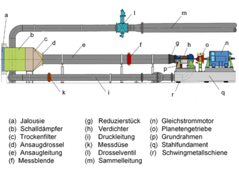
Description
Applicable measurement techniques a the high-speed compressor facility are comprised of a variety of conventional probes extending from steady- and unsteady-state multi-hole probes to CTA probes. Multiple measuring positions are available for these probes upstream and downstream of each blade row. Additionally, the compressor-testing environment can be equipped with a L2F system for optical flow measurements downstream of the third-stage stator.
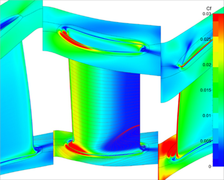
Experimental results of the compressor flow are supplemented with results of computational fluid dynamics (CFD) simulations. This procedure results in an experimental validation of numerical simulation results and facilitates the numerical investigation of flow phenomena which are too complex to be obtained experimentally.
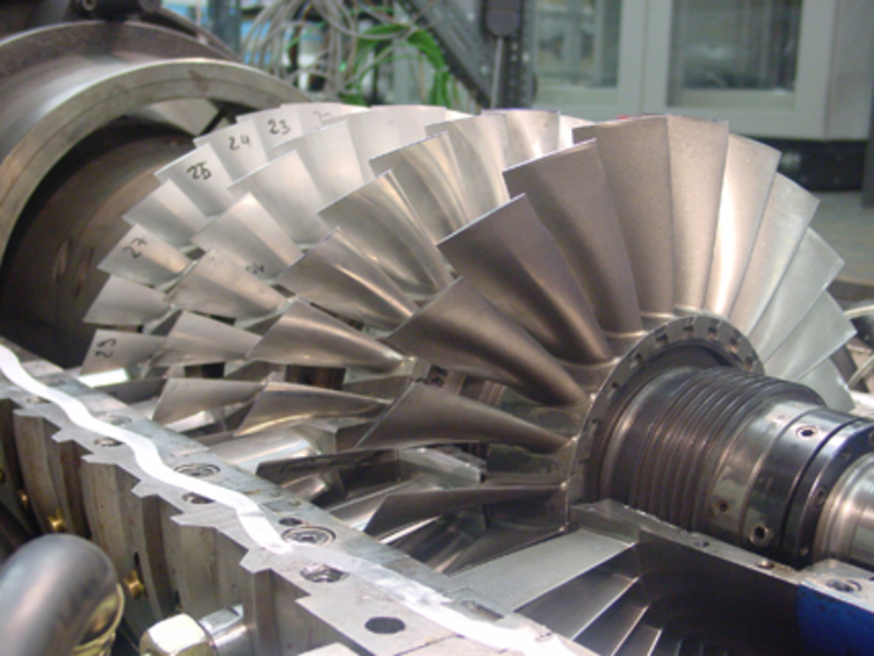
In recent years, major investigations related to the reduction of secondary flow losses using three-dimensional blade shapes with bow and sweep, as well as endwall contouring have been performed a high-speed compressor facility at TFD. Additionally, the phenomenon of acoustic resonance in compressors has been observed and proven experimentally by Hellmich in 2008. Currently, research projects which are focusing on methods for active flow control are being carried out with the four-stage configuration. The control methods considered include the injection of high-momentum fluid as well as the suction of low-momentum fluid. Simultaneously, the secondary flow losses of the 4.5-stage tandem configuration are being investigated experimentally.
Measurement Techniques
- Steady and unsteady pressure sensors
- Temperature sensors (type K and Pt100)
- Combined radial and peripheral traversing downstream of each stator row using steady and unsteady multi-hole flow-vector probes
- Radial traversing downstream of each rotor row using steady and unsteady multi-hole flow-vector probes
- Determination of velocity vectors and turbulent characteristics of the flow field by using constant temperature anemometry (CTA) and constant current anemometry (CCA)
- Application of Laser-2-focus (L2F) system between rotor and stator of the third compressor stage
- Optional tip-timing system
- Vibration control using acceleration sensors
- Torque measurement using a torque shaft
Specifications (Four-Stage Configuration)
| Number of stages | 4 |
| Rotational speed | 18.000 1/min |
| Mass-flow rate | 8.11 kg/s at 60 kPa total inlet pressure |
| Pressure ratio (total-to-total) | 2,87 |
| Power input | max. 950 kW |
| Inlet pressure (variable) | approx. 55 - 95 kPa |
Contact

Compressor
30823 Garbsen
Compressor


